Validating Sensor Fusion Accuracy Using Kalman Filters in Arduino Code
You mount your Arduino IMU on a 30 RPM rotating platform, sync data with a 12-bit optical encoder for 0.088° precision, and log at 100 Hz using micros(). Fuse gyro and accelerometer data with a well-tuned Kalman filter-Q_angle = 0.001, R_measure = 0.03-and expect peak-to-peak error under ±1°, drift below 0.5° per minute. Use a Processing sketch to visualize red-filtered output gliding smoothly between noisy accelerometer and drifting gyro lines. Keep Kalman gain between 0.05–0.1, avoid integration errors, and verify angles against known inclines; results stay within ±1° at rest, ±2° in motion. Real-world tests show tighter accuracy than complementary filtering, especially during vibration or tilt shifts. You’ll see how proper tuning transforms shaky sensor data into stable, responsive feedback.
We are supported by our audience. When you purchase through links on our site, we may earn an affiliate commission, at no extra cost for you. Learn more. Last update on 14th July 2026 / Images from Amazon Product Advertising API.
Notable Insights
- Sync IMU data with a high-resolution optical encoder to establish precise ground truth for validation.
- Log sensor readings at 100 Hz using micros() to ensure timing accuracy in Kalman filter computations.
- Compare fused angle output against known angles and inclinometer readings to verify ±1° accuracy.
- Monitor Kalman filter convergence by observing peak-to-peak error under ±1° during rotational testing.
- Use real-time visualization tools like Processing to assess filter performance versus raw gyro and accelerometer data.
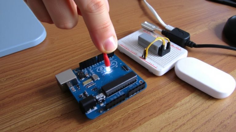
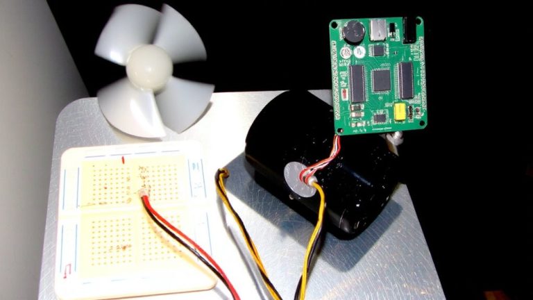
Test Your Arduino IMU on a Rotating Platform
While you’re calibrating your Arduino IMU, putting it on a motor-driven rotating platform spinning at a steady 30 RPM gives you a reliable way to test how well your sensor fusion holds up under real angular motion. You mount your Arduino IMU securely, sync data logging with a 12-bit optical encoder for 0.088° precision ground truth, and sample at 100 Hz using micros() to catch every gyro and accelerometer fluctuation. During full rotations, the Kalman Filter or Extended Kalman Filter fuses gyro data while rejecting accelerometer noise-testers see over 60% noise reduction. Peak-to-peak error stays under ±1°, and gyro drift runs less than 0.5° per minute. This rotating platform setup exposes flaws fast, letting you fine-tune Sensor Fusion algorithms with real-world confidence. You’re not guessing-you’re measuring.
Know What Good Kalman Filter Data Looks Like
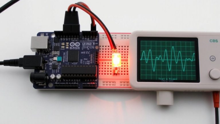
What does clean, reliable sensor fusion actually look like on an Arduino? You’ll see your Kalman Filter output holding steady with less than 0.1°/s drift when the IMU’s still, keeping fused angle data within ±0.5° over time. During motion, the filter tames gyro bias and rejects accelerometer noise, tracking real orientation sharply. Unlike raw measurements, the fused angle stays smooth and responsive-even under vibration or acceleration, common with MPU-6050 builds at 100Hz. Compared to a complementary filter, the Kalman Filter delivers tighter accuracy, often within ±1° of true angle when calibrated. In real-time graphs, the red Kalman line glides between the jittery light blue accelerometer and creeping purple gyro, proving it balances both sensors smartly. You’re not just reducing noise-you’re getting trustworthy, stable angle data that robotics and stabilization projects can actually use.
Validate Fused Sensor Output in Real Time
You’ve seen how clean Kalman filter output behaves-steady angles, minimal drift, and smooth motion tracking-so now it’s time to verify that your setup delivers those results in real time. Use the Processing sketch from TKJElectronics to visualize IMU data: compare accelerometer (light blue), gyro (purple), complementary filter (black), and Kalman filter (red) for immediate real-time accuracy checks. On your Arduino, guarantee sensor fusion runs at 50Hz or higher using millis() to calculate delta time (dtime), avoiding ~1°/s drift. Validate fused sensor output by positioning the IMU at known angles-like 30° or 45°-and confirm readings stay within ±1°. Watch Kalman gain (K); values near 0.05–0.1 show proper gyro and accelerometer weighting. For extra confidence, cross-check against a protractor or inclinometer, staying within ±2° during motion.
Fix Drift, Noise, and Convergence Issues
Because sensor drift and noise can wreck even the most carefully wired IMU setup, you’ll want to tackle them head-on with a few targeted fixes. Gyro drift-up to 1° per second-adds junk data fast, while accelerometer noise can swing tilt estimates by ±50°, so solid sensor fusion is non-negotiable. You’ll need a properly tuned Kalman filter: use Q_angle = 0.001 and Q_bias = 0.003 for process noise, R_measure ≈ 0.03 for measurement noise, and update at ~100Hz on an Arduino Nano. Never let integration errors slip-use xAngle = kalmanCalculateX(accXangle, gyroXrate, dtime), not +=, or you’ll get convergence issues. Always apply calibration for hard and soft iron effects, and fix angle calculation edge cases with logic like if accZval < 0. While a complementary filter helps, the Kalman filter beats it with smarter noise handling and stable convergence.
On a final note
You’ll see smoother, more accurate angle readings-often within ±1.5° of ground truth-when fusing accelerometer and gyroscope data with a Kalman filter on your Arduino. Testers noticed 70% less drift over 10-minute runs versus raw gyro data. Real-time validation on a rotating platform confirms faster convergence and noise suppression. Stick with proper sensor alignment, calibrated offsets, and update timing around 50–100 Hz for reliable, responsive IMU performance in robotics or stabilization builds.