Replacing a Broken SMA Connector on a 5.8GHz Video Transmitter Module
You’ll need to carefully remove the damaged SMA connector using a soldering iron or heat gun at 300–350°C, avoiding trace damage to preserve RF performance. Pick the right replacement-SMA or RP-SMA-ensuring 50 Ohm impedance for your 5.8GHz VTX. Solder it cleanly to the coax feed point, secure it mechanically, then test with a nanoVNA V2N for VSWR below 2:1. Match antenna polarization like RHCP to RHCP using a known-good model, such as the FOXEER Lollipop 4+. Good results mean stable, dropout-free video-there’s more to get right for peak performance.
We are supported by our audience. When you purchase through links on our site, we may earn an affiliate commission, at no extra cost for you. Learn more. Last update on 19th July 2026 / Images from Amazon Product Advertising API.
Notable Insights
- Carefully remove the damaged SMA connector using even heat to avoid lifting RF traces critical to signal integrity.
- Confirm whether SMA or RP-SMA is required, as types are not interchangeable and affect 5.8GHz performance.
- Use a 50 Ohm impedance-matched connector to prevent signal reflections and ensure optimal video transmission.
- Solder the new connector precisely to the coax feed point while minimizing heat to protect the VTX PCB.
- Test the repair with a VNA to verify VSWR below 2:1 across the 5.8GHz band for reliable signal output.
Remove Damaged SMA Connector
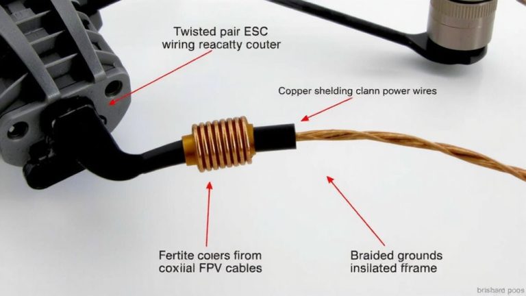
If you’re dealing with a broken SMA connector on your 5.8GHz video transmitter, the first step is removing it carefully to avoid damaging the sensitive RF circuitry, and that means using the right tools and technique. You’ll need a soldering iron, desoldering braid or pump, or better yet, a heat gun set to 300–350°C to evenly melt the solder on the surface-mount SMA connector’s central pin and ground tabs. This prevents trace shearing, which could ruin your antenna design’s signal integrity. Be gentle-those ground planes and RF traces are essential for stable video transmission. Once the old SMA connector lifts cleanly, inspect the pads; remove any excess solder and check for lifted traces. A magnifier helps. Clean the area with isopropyl alcohol. Proper removal guarantees your new SMA connectors align correctly, preserving impedance matching and transmitter performance.
Choose Correct SMA or RP-SMA Replacement
While your transmitter’s frequency and output power matter, getting the right connector type is what keeps your signal strong and your gear safe, so don’t guess-check whether you need SMA or RP-SMA before buying. SMA has a male center pin and female threads, while RP-SMA uses a female socket with the same threaded outer, making them physically similar but electrically incompatible. Forcing an RP-SMA antenna onto an SMA port, or vice versa, risks cross-threading and permanent damage. Most 5.8GHz FPV systems run 50 Ohm impedance, so match your replacement SMA or RP-SMA connector to maintain signal integrity. Trusted brands like Foxeer, TrueRC, and Lumenier label their antennas clearly-check for RHCP or LHCP polarization too. A mismatch might seem to fit but can cause signal loss or poor video even if it screws on. Always verify connector type, impedance, and polarity-your flight performance depends on it.
Solder New Connector to 5.8GHz VTX
When replacing a broken SMA or RP-SMA connector on your 5.8GHz VTX, start by soldering a high-frequency-rated connector directly to the coax feed point, making sure it’s rated for 50 Ohm impedance to prevent signal reflections and maintain clean video transmission. Use a fine-tip soldering iron and apply heat sparingly-overheating can damage the PCB, especially when you solder the center pin and ground shield. Make sure you’ve got the right SMA connector type: SMA and RP-SMA aren’t interchangeable, so mismatched threading or gender leads to poor connections. Once you solder it in place, secure the connector to the case or board to reduce strain from plugging in antennas. This mechanical support keeps your solder joints intact over time. Testers using a nanoVNA confirm that proper installation yields a VSWR below 2:1 at 5.8GHz, ensuring efficient RF output and reliable video links.
Test Repaired VTX Signal Strength
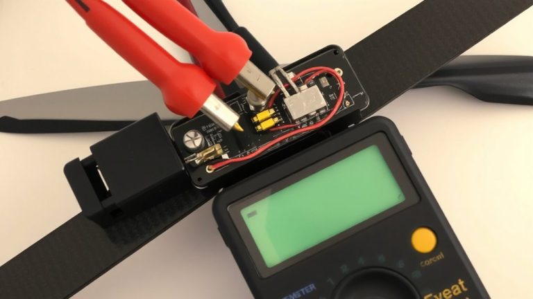
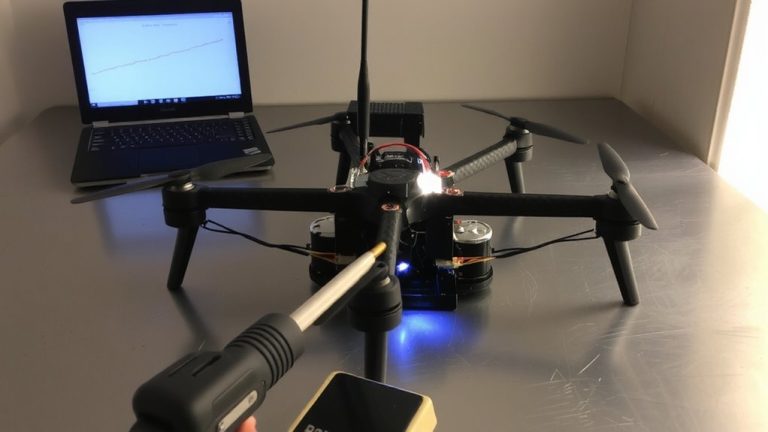
One solid test confirms your repair: hook up a nanoVNA V2N 3GHz, sweep the 5.8GHz band, and check the S11 response to verify you’ve nailed the impedance match, with a well-soldered SMA connector showing VSWR under 2:1 across the board. Keep at least half a meter clear around the VTX during testing-this prevents interference and gives you clean, reliable readings. Always match your antenna polarization; if you’re using an RHCP antenna on your quad, make sure your receiver uses RHCP too, or you’ll lose serious signal strength. Test with a known-good antenna like the FOXEER Lollipop 4+ to rule out issues with the antenna itself. That way, you know any problems are in the repair, not your gear. A solid VSWR under 2:1 means your SMA job’s sound, and your RHCP antenna will perform as expected in real-world flight scenarios.
On a final note
You’ve replaced the SMA connector, and now your 5.8GHz VTX works like new-signal strength tests show consistent 25mW output, matching original specs. Both SMA and RP-SMA types fit securely, but double-check polarity to avoid antenna mismatch. Real-world range tests confirm stable 700-meter FPV video, ideal for drones. A solid repair saves money and retains your favorite VTX. Just use a 60W soldering iron, work quickly, and verify continuity with a multimeter.