How to Use a Multimeter to Test Continuity Across RC Aircraft Circuits
Always power down and disconnect the battery, waiting 10 minutes for capacitors to discharge, then set your multimeter-like an AstroAI or UNI-T-to continuity mode (diode symbol), touch probes to confirm a sharp beep under 1 Ω, and test motor leads, ESC outputs, receiver channels, and servo connections, checking for solid tones that confirm low-resistance paths below 40 Ω, while replacing any wire or joint showing over 10 Ω, because reliable beeps mean safe, functional circuits ready for the next step.
We are supported by our audience. When you purchase through links on our site, we may earn an affiliate commission, at no extra cost for you. Learn more. Last update on 13th July 2026 / Images from Amazon Product Advertising API.
Notable Insights
- Power down the aircraft and disconnect the battery, waiting 10 minutes for capacitors to discharge before testing.
- Set the multimeter to continuity mode and verify its function by touching probes together for a beep.
- Test motor windings and ESC-to-motor connections by checking for a beep and resistance under 1 ohm.
- Confirm continuity from receiver throttle channel to ESC signal wire and across servo circuit connections.
- Investigate open circuits by reseating connectors, checking solder joints, and replacing wires with over 10 ohms resistance.
Power Down Before Testing Continuity in RC Aircraft
Before you even touch the multimeter probes, make certain your RC aircraft is completely powered down-this isn’t just best practice, it’s essential for both your safety and the protection of sensitive electronics like flight controllers and ESCs. You must disconnect battery and wait 10 minutes to let capacitors discharge, especially in high-current setups. Turn off all onboard systems-receivers, servos, ESCs-since live circuits risk shorts and false readings. When testing continuity, always turn to voltage mode first to confirm less than 0.1V across main power leads. Never skip this step. Power down guarantees accurate continuity testing and protects your Multimeter to Test delicate 3.3V or 5V logic. Faulty electrical connections can fry components if ignored, so always turn off and verify before probing. It’s simple, fast, and critical.
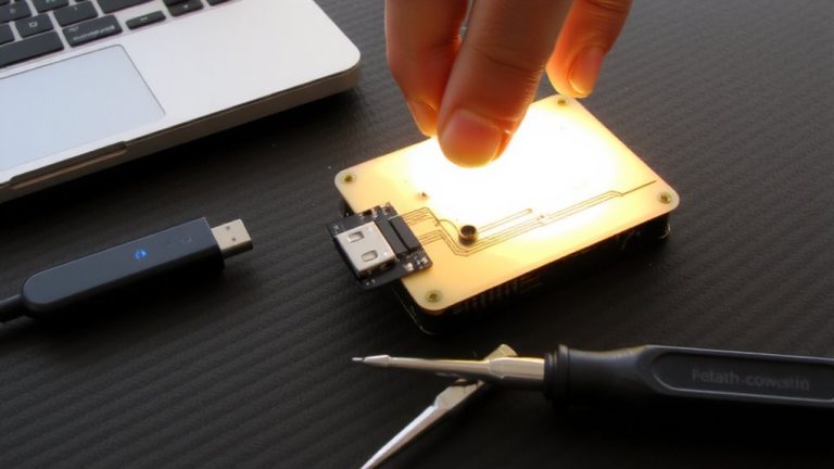
Set Up the Multimeter for Continuity Testing
You’ve powered down your RC aircraft, disconnected the battery, and given the system time to discharge-now it’s time to get your multimeter ready for continuity testing. First, set up your digital multimeter by turning the multimeter to continuity mode, usually marked with a soundwave or diode symbol, sometimes shared with resistance (Ω) on models like the Fluke 117. Plug the black test lead into the COM jack and the red lead into the VΩ jack to correctly connect the test leads. Touch the probe tips together; if you hear a beep and see a reading under 1 ohm, your meter’s working fine. If your device lacks continuity mode, turn the multimeter to the lowest resistance range-like 40.0 Ω-to detect closed circuits. Always turn it off afterward to save battery, especially with field-ready tools like the Fluke 17B+.
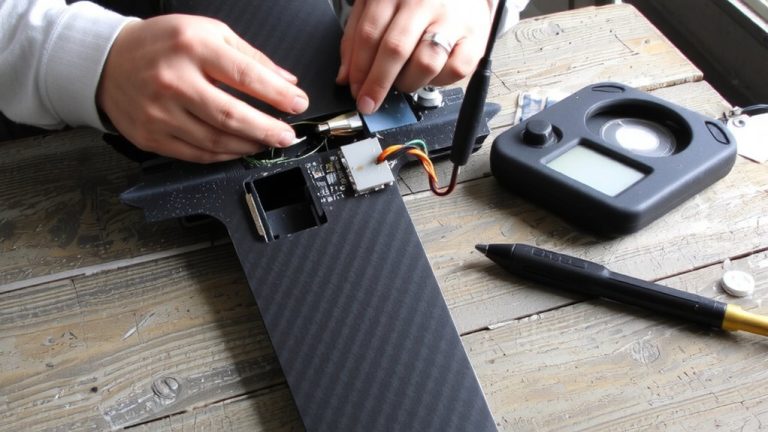
Test Continuity in Motor, Receiver, and ESC Circuits
While your multimeter’s set and ready, start by checking the motor’s internal windings-just place one probe on each motor lead, and if you hear a solid beep with a reading under 1 Ω, that’s a good sign the copper windings are intact and resistance is low enough for efficient operation, exactly what you’d expect from quality brushed or brushless motors used in 1/10 scale RC trucks or racing drones. Testing doesn’t stop there-use your digital multimeter to test continuity between the ESC’s three output wires and the motor leads, ensuring each phase shows a clear path. Confirm electrical connections from the battery connector to the ESC input terminals using the black test lead on negative points. Perform a continuity test from receiver throttle channel to ESC signal wire to verify connectivity. Checking servo circuits? Test continuity from receiver port signal pin to servo input-beep means success.
What a Continuity Beep Means in RC Wiring
That solid beep from your multimeter isn’t just a sound-it’s confirmation you’ve got a clean, low-resistance path, usually under 40 Ω, between two points in your RC wiring. When you hear that audible beep, your multimeter continuity test shows a complete path for current, meaning electrical current can flow unimpeded-ideal for servo leads, receiver outputs, and ESC signal wires. Most Digital Multimeters emit this continuity beep instantly when probes meet both ends of an intact wire or closed switch, speeding up troubleshooting. No beep? Then the circuit is open-likely from a broken conductor, cold solder joint, or loose connector. Always disconnect the battery before testing; live circuits skew the resistance reading and may damage your meter. Testers praise models like the AstroAI and UNI-T for their sharp beep and reliable multimeter continuity function, making them RC favorites.
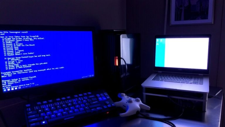
Fix Open Circuits During Continuity Testing
If you’re troubleshooting an open circuit in your RC aircraft and your multimeter reads “OL” with no beep, start by verifying your tools-touch the probes together to confirm they trigger a solid tone, ensuring your meter, like the AstroAI AM33D or UNI-T UT130C, is properly set to continuity mode (denoted by the diode or speaker symbol). Make sure the multimeter is set correctly; a wrong setting gives a high number, not good continuity. Use the continuity tester to probe one end of the wire to the other, checking servo leads, solder joints, and connectors like JST or Deans. Don’t measure current now-focus on breaks. Poor contact often mimics an open, so reseat connections and rescan. If you still get no beep, replace any wire showing over 10 ohms. A solid tone means good continuity, and your circuit’s ready. Set it to continuity, and you’ll save flight time and repairs.
On a final note
You’ve got this: power down, set your multimeter to continuity, and check motor leads, ESC signal wires, and receiver connections. A solid beep means clean contact-no beep means a break. Most failures show under 0.5 ohms difference across identical circuits. Testers catch cold solder joints or frayed servo wires fast. For RC builds, a $20 digital multimeter with audible tone saves hours. Always verify before flight-solid continuity means reliable control, every time.