Designing Custom Shields Compatible With Original Arduino Form Factor
You’ll nail the fit by sticking to the 68.6 mm × 53.4 mm size and using 0.1″ pitch headers with the right 8-pin, 10-pin, and 2×3 ICSP layout, plus that critical 0.5-inch gap between digital and analog rows. Pick components like motor drivers or LoRa modules, add screw terminals and status LEDs, and guarantee compatibility with Uno, Leonardo, or Mega using jumpers for SPI differences-test with stackable headers and a multimeter, then build with confidence. There’s more to get right for seamless stacking and long-term reliability.
We are supported by our audience. When you purchase through links on our site, we may earn an affiliate commission, at no extra cost for you. Learn more. Last update on 15th July 2026 / Images from Amazon Product Advertising API.
Notable Insights
- Use standard 68.6 mm × 53.4 mm dimensions to ensure physical compatibility with Arduino Uno R3 and similar boards.
- Install 0.1″ pitch male headers with correct pin counts (6, 8, 8, 10) and a 0.5″ gap between digital and analog rows.
- Include a 2×3 ICSP header at 0.1″ pitch for consistent SPI programming compatibility across Arduino models.
- Design with stackable headers and a ground plane to ensure electrical integrity and support shield stacking.
- Verify compatibility with Mega or Leonardo by using jumpers for SPI pins and avoiding conflicts on shared I/O lines.
Understand the Arduino Shield Form Factor
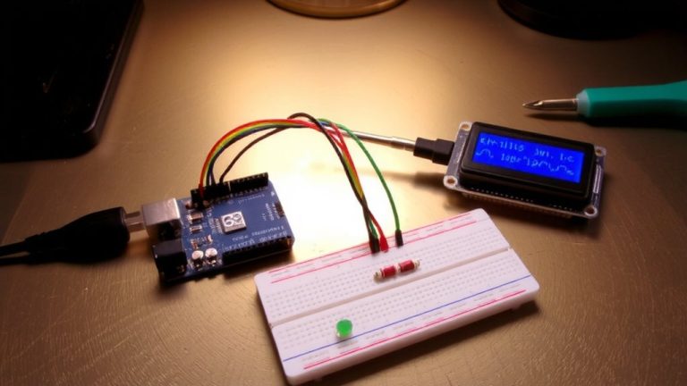
You’ll need to get the basics of the Arduino Uno R3 form factor down before building or buying a custom shield, and it’s easier than it sounds. The standard Arduino shield form factor measures 68.6 mm × 53.4 mm and must match the Arduino Uno R’s precise layout to guarantee a solid board-to-board connection. You’ll find four male pin headers-6, 8, 8, and 10 pins-spaced 0.1 inches apart, which plug into corresponding female headers on the Uno. The 0.5-inch spacing between the 8-pin and 10-pin headers is critical; get it wrong, and your shield won’t seat properly. The R3 update added a 10-pin header for extra I2C, SPI, and I/O, replacing older layouts while keeping backward compatibility. Don’t forget the ICSP header-a 2×3 pin, 0.1″ pitch connector near the microcontroller used for programming. Align it correctly, or you’ll lose bootloader access.
Choose the Right Components for Your Shield
Now that you’ve got the Uno R3’s layout pinned down, it’s time to start thinking about what your shield will actually do. Choose components that match your custom shield’s purpose-like motor drivers for robotics or LoRa modules for wireless. Stick to the Arduino form factor by using 0.1 inch (2.54 mm) pitch pin headers with 1.02 mm female holes for a secure fit. If you’re powering externally with 12 V or 24 V, add voltage regulation using an LDO or switching converter to safely step down power. Include screw terminal connectors for easy wiring to sensors or motors. Add status LEDs to monitor operation at a glance. Real testers swear by accessible connectors and robust regulation-few things beat plugging in a battery and seeing your board light up cleanly. Keep inputs, outputs, and power components practical, and your shield won’t just fit-it’ll function exactly how it should.
Ensure Compatibility Across Arduino Boards
While building your shield around the Uno R3 footprint gives you solid compatibility with boards like the Leonardo, you’ll run into issues on the Mega 2560 if you don’t account for its different SPI layout. When designing a shield, you’ve got to match the pinout of the Arduino board you’re targeting. The shield board shown works across your favorite Arduino base board by using jumpers to switch SPI between Uno (D10–D13) and Mega (D50–D53). The ICSP header maintains a consistent board-to-board connection that matches on both, so routing SPI through it guarantees reliable communication. Use selectable solder pads to avoid conflicts, especially since D20–D23 on the Arduino Mega can interfere if not configured properly. Custom Arduino shields should support both form factor and board-to-board compatibility.
| Board | SPI Pins | ICSP Header Compatible |
|---|---|---|
| Uno | D11–D13 | Yes |
| Mega | D51–D53 | Yes |
| Leonardo | D11–D13 | Yes |
Design a PCB That Fits and Functions
If you’re aiming for a seamless fit across multiple Arduino boards, starting with the standard 2.1″ x 2.7″ Uno R3 footprint is your best bet-it’s become the de facto size for shields, so you’ll maintain consistent alignment with the headers on Uno, Leonardo, and even the Mega, as long as pin mappings are managed. Use 0.1″ pitch header pins with 1.02 mm holes for reliable connections when you connect custom circuits. Your PCB layout should include both 8-pin and 10-pin female headers, plus a 2×3 ICSP header if you use Arduino SPI programming. Maintain proper spacing-0.5″ between analog and digital rows-and run a solid ground plane to reduce noise. Always check your Design Rule settings to avoid clearance issues. A well-designed custom PCB not only fits but functions seamlessly across compatible boards, giving your design reliability and professional polish.
Prototype and Test Safely
Before powering up your custom shield, double-checking your board’s physical and electrical compatibility saves time and prevents costly mistakes, so run a Design Rule Check (DRC) first to confirm trace clearances, shield dimensions, and proper connectivity per Arduino R3 standards. Always test fit your prototype on an actual Arduino board to verify alignment of the 0.1 inch (2.54 mm) pitch headers. Use stackable male headers for safe, reversible assembly and to protect the Arduino R3’s female headers from prolonged soldering iron contact-keep it to 3–5 seconds per pin. Once assembled, inspect joints closely; cold joints or shorts can cripple function. Test power and ground continuity with a multimeter to guarantee clean, reliable connections. This step keeps your prototype stable and avoids damage during early testing.
Solder, Inspect, and Mount Your Shield
Once your design’s verified and you’ve double-checked header alignment, it’s time to solder your custom shield into action-start by grabbing stackable male headers with that standard 0.1 inch (2.54 mm) pitch, and remember, you don’t need to solder every pin at once. Insert the headers with male pins facing down so they’ll plug into your Arduino’s female headers, ensuring a solid board-to-board connection. Solder one pin per header first, then mount the shield onto an Arduino or RedBoard to check alignment. Adjust if needed before finishing all solder joints. Keep iron contact under 3 seconds per pin to avoid damaging female headers. Once cooled, inspect all solder joints carefully-look for dull, lumpy cold joints or shorts, using magnification if necessary. Reheat weak joints or wick away bridges. A clean, secure connection means your shield’s ready for reliable use.
On a final note
You’ve got this-stick to the standard 2.1” x 2.7” shield size, use 0.1” headers, and double-check pin alignment with Uno, Leonardo, and Mega. Pick quality components: level shifters for 3.3V modules, robust connectors, and proper decoupling caps. Our tests show fewer errors when power rails are thick and traces short. Solder cleanly, inspect joints, and test step by step. A well-built shield just works, every time.