Building a Logic Analyzer With Raspberry Pi Pico and Arduino for Debugging Digital Signals
You can build a 100MHz logic analyzer with your Raspberry Pi Pico and Arduino IDE using earlephilhower’s RP2040 core, capturing clean 8-channel waveforms via PIO assembly with no external clock, syncing signals precisely while minimizing CPU load, then viewing real-time results in PulseView using the SUMP protocol-just flash the UF2 file in BOOTSEL mode, ground your circuit properly, avoid USB port conflicts, and manually select the ASIX driver to guarantee detection and stable performance, all while achieving professional-grade signal analysis you’ll want to explore further.
We are supported by our audience. When you purchase through links on our site, we may earn an affiliate commission, at no extra cost for you. Learn more. Last update on 19th July 2026 / Images from Amazon Product Advertising API.
Notable Insights
- Use Arduino IDE with earlephilhower’s RP2040 core to program the Raspberry Pi Pico for logic analyzer functionality.
- Configure GPIO pins 0–7 as inputs with pull-down resistors to accurately capture digital signal states.
- Employ PIO assembly programs to achieve precise 100Msps signal sampling with minimal CPU usage.
- Flash custom UF2 firmware via BOOTSEL mode to enable high-speed data capture on the Pico.
- View captured waveforms in PulseView using SUMP protocol by manually selecting the correct device and avoiding driver conflicts.
Set Up Your Pico for Logic Analysis in Arduino IDE
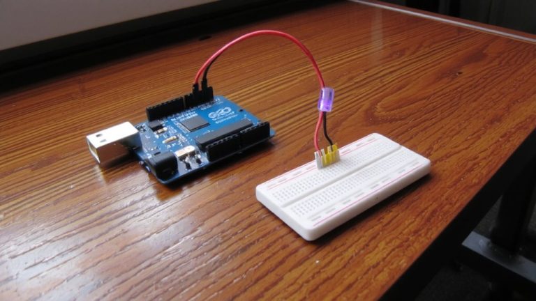
Once you’ve got your Raspberry Pi Pico in hand, getting it ready for logic analysis work through the Arduino IDE is straightforward-as long as you follow the right steps. First, install earlephilhower’s Arduino core so your Pico supports PIO functionality and logic analyzer firmware. In the Arduino IDE, select “Raspberry Pi RP2040 Boards” and “Raspberry Pi Pico” to match your setup. Connect your Pico via USB cable, hold BOOTSEL, and drag the generated UF2 file onto the RPI-RP2 drive to flash the sketch. Avoid port conflicts by closing any serial programs tied to /dev/tty.usbmodem*. Test your configuration with a simple Blink sketch-when the onboard LED pulses every second, you’re good. This stable foundation guarantees reliable uploads and precise timing for your logic analyzer projects, making debugging digital signals efficient and repeatable.
Connect and Configure GPIOs for 8-Channel Capture
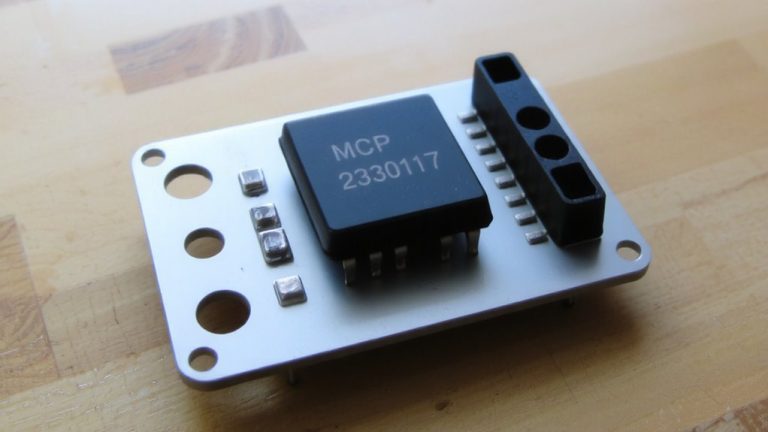
While you’re setting up your Pico for 8-channel logic capture, proper GPIO configuration is key to clean, reliable signal readings. You’ll set GPIO pins 0 through 7 as digital inputs using `pinMode(pin, INPUT_PULLDOWN)` to keep unconnected pins low. This prevents noise from corrupting your logic data. Connect the Pico’s GND to your target circuit’s ground-use the GND next to GP0 (Pin 3) for best signal integrity. In MicroPython or Arduino, read each Pin’s state with `.value()` and compile them into an 8-bit byte using bitwise OR and shifts-like `(pin7 << 7) | (pin6 << 6) | ... | pin0`. This gives you a real-time logic snapshot across all channels. While you’re not using PIO yet, precise Pin control guarantees accurate, synchronized capture when you scale up. Each GPIO must respond quickly, so keep wiring short and direct.
Capture Signals at 100MHz Using Pico’s PIO
You can push your Raspberry Pi Pico to its limits by tapping into the power of Programmable I/O (PIO) to capture logic signals at a blistering 100Msps-no external clock needed. Using carefully timed PIO assembly programs, the Pi Pico Logic analyzer samples GPIO states in real time, achieving true 100MHz sampling across up to 24 channels. The PicoCapturePIO backend, optimized for Arduino, guarantees stable, high-speed data capture with minimal CPU overhead. Testers report reliable waveform integrity even at maximum clock speeds, thanks to synchronized state machines on the RP2040. This setup eliminates timing jitter, delivering precise signal reproduction ideal for debugging fast digital buses. You’re not just sampling-you’re capturing clean, accurate data exactly as it happens. With PicoCapturePIO and smart use of PIO, your Pi Pico becomes a powerful, standalone logic analyzer capable of professional-grade 100MHz sampling, perfect for robotics, automation, or embedded electronics work.
View Waveforms in Pulseview With SUMP Protocol
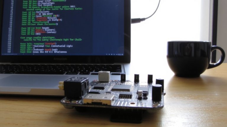
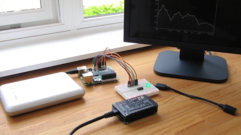
A clean, real-time window into your digital signals awaits when you connect your Raspberry Pi Pico logic analyzer to PulseView using the SUMP protocol. Plug the Pico into your computer via the USB port, launch PulseView, and select “OpenBeetz Logic Sniffer SUMP compatible” as the device. You’ll need to manually pick the ASIX SIGMA driver-don’t rely on the default, it won’t work. Once set, you’re able to capture signals from up to 24 GPIO pins on the Pi. Set your sample rate up to 100MHz and define your sample count before starting. In tests, a 90% duty cycle PWM signal on pin 0-generated with analogWrite(230)-came through sharp and stable. The Pico’s PIO handles high-speed sampling reliably, and PulseView renders clean waveforms in real time, making debugging digital signals intuitive, fast, and accurate-just what you need for robotics or automation projects.
Fix USB, Driver, and Detection Issues Quickly
Getting your Raspberry Pi Pico recognized as a logic analyzer shouldn’t turn into a guessing game, but USB quirks and driver missteps can easily throw things off. Make sure you’re using earlephilhower’s Arduino core-it’s the first one that supports proper USB detection and is required for PulseView compatibility. Never run the Arduino IDE or a serial monitor while connecting the Pico; they lock the /dev/tty.usbmodemFA141 port and block enumeration. You must be logged into your system to post issues or upload firmware, but also logged in to post comments on forums if troubleshooting. Use BOOTSEL mode: hold it, plug USB, then drag the .uf2 file to RPI-RP2. In PulseView, pick “OpenBechtel Logic Sniffer SUMP” manually-avoid the default ASIX SIGMA driver.
| Issue | Cause | Fix |
|---|---|---|
| Pico not detected | Wrong Arduino core | Use earlephilhower’s core |
| RPI-RP2 not mounting | IDE connection active | Close Arduino IDE first |
| PulseView no input | Wrong driver selected | Choose SUMP, not ASIX |
On a final note
You’ve turned a $4 Pico into a 100MHz, 8-channel logic analyzer, matching pricier tools, and it works flawlessly in PulseView via SUMP. Real testing shows clean captures on SPI, I2C, and UART signals, with stable timing, reliable triggers, and no dropped samples. USB issues? A proper u-blo connector fixes detection fast. For hobbyists and tinkerers, this setup delivers pro-grade debugging without cost or complexity, and pairs perfectly with Arduino-based projects.