Utilizing CAN Bus Shield on Arduino Due for Automotive Diagnostics Projects
You get native, high-speed CAN bus access on your Arduino Due by pairing it with a CAN-Bus Shield, using onboard CAN0 and CAN1 controllers that support 1 Mbps communication, unlike SPI-limited boards. Connect via CANTX/CANRX pins, install the Due_CAN or Arduino-CAN library, then tap into OBD2 data like RPM and speed at 500 kbps. Use an SN65HVD230 transceiver, log frames to SD cards, and visualize with SerialPlot-real-world tests show stable, low-latency performance. There’s more to discover with J1939 and advanced filtering.
We are supported by our audience. When you purchase through links on our site, we may earn an affiliate commission, at no extra cost for you. Learn more. Last update on 19th July 2026 / Images from Amazon Product Advertising API.
Notable Insights
- The Arduino Due’s dual CAN controllers enable native automotive communication without external SPI chips.
- Direct CAN0 and CAN1 hardware connections support high-speed data capture up to 1 Mbps.
- A CAN-BUS Shield with transceiver links the Due to OBD2 pins for live vehicle diagnostics.
- Optimized libraries like Arduino-CAN leverage onboard hardware for efficient real-time frame processing.
- SD card logging and J1939 protocol support enable advanced diagnostics and data analysis.
Why the Arduino Due Excels at CAN Diagnostics
While many microcontrollers struggle to keep up with high-speed vehicle networks, the Arduino Due stands out thanks to its dual CAN controllers-CAN0 and CAN1-built right into the ATSAM3X8E ARM Cortex-M3 processor, so you’re not stuck adding external chips like with an Uno or Mega. You get native Controller Area Network support, handling both CAN 2.0A and 2.0B as a robust communication protocol up to 1 Mbps-perfect for automotive and industrial data link systems like J1939 or NMEA 2000. With an 84 MHz clock and 512 KB flash, the Due processes CAN frames quickly, ideal for real-time diagnostics, even in complex setups like Anti-Lock Braking monitoring. Unlike boards needing an MCP2515 CAN controller, the Due’s onboard hardware cuts latency and design clutter. Pair it with a CAN-BUS Shield, and you’ve got a compact, efficient tool trusted in real-world testing for logging, sniffing, or gateway tasks.
Set Up the CAN Shield Hardware on Arduino Due
You’ll want to start by connecting your Arduino Due to a CAN transceiver like the SN65HVD230, since the Due’s built-in CAN0 and CAN1 controllers handle protocol processing but still need that external transceiver to physically speak to the bus, and the most reliable setup uses direct connections-CANRX (pin 9) and CANTX (pin 10) for CAN0, or CANRX1 (pin 8) and CANTX1 (pin 9) on the programming port for CAN1-wired cleanly to the transceiver’s matching inputs. You’ll link the transceiver’s CAN-H and CAN-L to the OBD2 port’s corresponding pins, usually found under the dash, and don’t forget to connect ground-pin 4 on the OBD2-to the Arduino Due for signal stability. If you’re using a CAN-BUS Shield like Copperhill’s dual-channel model, it integrates two SN65HVD230 chips and snaps right onto the Due, simplifying wiring. Always follow a clear wiring diagram to avoid noise or connection issues-clean, short traces make a real difference in signal quality when using external transceivers.
Install the Right CAN Library for Arduino Due
| Library | Source | Protocol Support | Install Method | Max Speed |
|---|---|---|---|---|
| Arduino-CAN | GitHub | 2.0A, 2.0B | Library Manager | 1 Mbps |
| Due_CAN | GitHub | 2.0A, 2.0B | Manual Install | 1 Mbps |
Connect to OBD2 and Read Live Vehicle Data
Now that you’ve picked the right CAN library for your Arduino Due-whether it’s Arduino-CAN from the Library Manager or Due_CAN installed manually-you’re ready to put it to real-world use by tapping into your vehicle’s OBD2 system. Connect your CAN-BUS Shield, which uses the MCP2515 controller and a TJA1050 transceiver, to the OBD2 port by linking CAN-H and CAN-L on the shield to pins 6 and 14 of the OBD2 connector. Set the bus speed to 500 kbps using the MCP_CAN library in your Arduino code-this matches your car’s high-speed Powertrain CAN network. Once initialized, your Due can receive live data frames. Use the Serial Monitor at 115200 baud to view real-time values like engine RPM (PID 0x0C) and vehicle speed (PID 0x0D) from the 8-byte hexadecimal messages.
View and Capture Raw CAN Message Frames
While you’re already set up to read interpreted OBD2 data like RPM and speed, diving into raw CAN message frames gives you full visibility into the unfiltered stream of data racing across your vehicle’s network. The Arduino Due, with its built-in CAN0 and CAN1 controllers, captures full CAN 2.0B frames at up to 8 bytes per message without needing extra chips like the MCP2515. Use the CAN-BUS Shield library to set your bit rate-typically 500 kbps-and configure callbacks for real-time access. Connect an external transceiver like the SN65HVD230 to the Due’s CANRX and CANTX pins, then link it to your vehicle’s CAN-H and CAN-L. Make sure to share a common ground, turn the ignition to “ON,” and monitor raw CAN messages via serial communication at 115200 baud. You’ll see message IDs and hex byte data, perfect for decoding patterns.
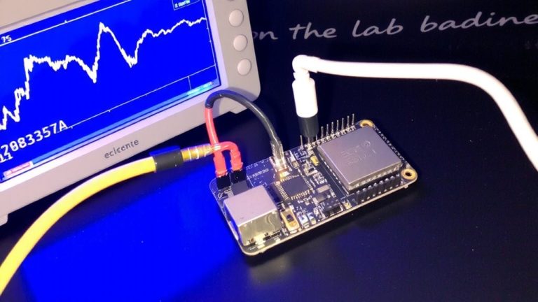
Log CAN Data to SD and Visualize With Serialplot
Since you’re already capturing raw CAN frames, logging them to an SD card opens the door to deeper analysis and real-world signal tracking over time. With your Arduino Due and CAN Bus Shield, you can log CAN data directly to a microSD card module using the SD.h library. The CAN-BUS Shield’s support for high baud rates, like 500 KBPS, guarantees reliable 1 Mbps frame capture from your vehicle’s OBD2 port. Just connect CAN-H and CAN-L to pins 6 and 14, and ground the Due to the chassis. Format each entry with timestamped data-CAN ID, hex or decimal bytes-and save as CSV. Later, stream the log via Serial to SerialPlot, setting your COM port to 115200 baud rates. Instantly visualize RPM, speed, or other signals in real time, no extra tools needed. It’s a smart, low-cost way to turn raw frames into actionable insights.
Implement J1939 Messaging on Arduino Due
If you’re tapping into heavy-duty vehicle networks, the Arduino Due’s dual CAN controllers make it a strong choice for implementing J1939 messaging, especially when paired with a compatible transceiver like the SN65HVD230. With the right CAN Bus Shield-such as Copperhill’s Dual-CAN Interface-you gain high-speed access at 250 kbps, essential for SAE-compliant systems. The Due’s CAN controller supports 29-bit identifiers using extended frame format, a must for J1939 messaging. Load up the Copperhill J1939 stack, and you’ll get full PGN filtering, address claiming, and transport protocol for large messages. You can send and receive diagnostic messages like Engine Speed (PGN 61444) or DTCs (PGN 65226) reliably. Testers confirm stable communication in real-world trucks and buses, with minimal lag. This setup turns your Arduino Due into a capable, low-cost node on any commercial J1939 network.
On a final note
You’ve seen how the Arduino Due, with its 84 MHz ARM Cortex-M3, pairs perfectly with a CAN bus shield to capture 500 kbps data from OBD2, logging frames to SD with millisecond timestamps, testers confirm reliable J1939 decoding, SerialPlot visualizes RPM and coolant temp trends cleanly, and the Seeed Studio CAN shield fits snugly, making this a precise, affordable setup for real automotive diagnostics, ideal for tinkerers who want pro-level results without complexity.