Setting Up Dual Telemetry Links Using Both Bluetooth and RSSI Outputs
You get reliable dual telemetry by pairing RSSI and Bluetooth-use the ZS-040 (HC-05 variant) set to 9600 baud, slave mode, with AT commands via 3.3V USB-TTL, then wire it to the Smart Port using a 2N7000 MOSFET to shift 5V down to safe 3.3V levels, enable “RSSI dBm value” in Betaflight OSD, disable RSSI_ADC, and test both links using EdgeTX alarms (LQ <50%, -98dBm threshold) and a Bluetooth Telemetry Viewer to confirm live voltage, GPS sats, and temperature reach your tablet. There’s more to get right the first time.
We are supported by our audience. When you purchase through links on our site, we may earn an affiliate commission, at no extra cost for you. Learn more. Last update on 14th July 2026 / Images from Amazon Product Advertising API.
Notable Insights
- Use RSSI for real-time signal strength monitoring from -30dBm to -130dBm in Betaflight OSD.
- Configure ZS-040 Bluetooth module to 9600 baud and slave mode for reliable telemetry streaming.
- Wire ZS-040 to Smart Port using a 2N7000 MOSFET to step down 5V to safe 3.3V logic levels.
- Enable dual telemetry by disabling RSSI channel in Betaflight and using OSD alarms at -98dBm.
- Test both links simultaneously using EdgeTX, Betaflight OSD, and Bluetooth Telemetry Viewer apps.
Why Use Bluetooth and RSSI for Dual Telemetry?
While you’re in the air, losing telemetry can mean losing control, so running both Bluetooth and RSSI gives you a backup link that keeps data flowing even if one system drops. You’re building redundant data links, and that’s critical for reliability. RSSI delivers real-time signal strength in dBm-watch it dip from -30 to -130dBm as range increases-so you can set precise OSD alarms like osd_rssi_dbm_alarm = -98. Meanwhile, your Bluetooth module, like the ZS-040, streams voltage (3.6V per cell), GPS satellites (0 to 12 near a window), and temperature directly to a tablet. You get EdgeTX LQ alerts (50% low, 20% critical) on your radio and live diagnostics via apps like Crazy Dudes-all without touching the RC link. This dual setup isn’t overkill; it’s smart redundancy that keeps you informed, safe, and in control.
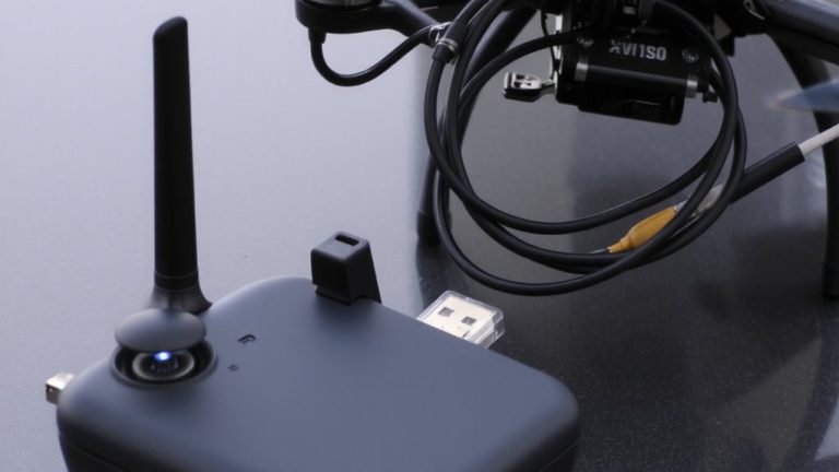
Get the Right Bluetooth Module: ZS-040 Setup Guide
Your ZS-040 Bluetooth module, a reliable HC-05 variant, is the backbone of a solid secondary telemetry link, and getting it set up right means you’ll have stable, real-time data streaming to your tablet without hogging your RC system. For proper ZS-040 setup, connect it to a USB-TTL adapter, cross RX to TX and TX to RX, then raise the EN pin to 3.3V during power-up to enter programming mode. Use terminal software like Termite with line endings set to CR + LF. Send “AT”; if you get “OK,” your module’s responding. That’s the first win in your ZS-040 setup. Keep configurations simple-rename it clearly using uppercase and underscores, like “AT+NAME=DRONE_LINK.” Most users will stay in slave mode, but confirm settings before moving forward. It’s hands-on, precise, and totally doable with basic gear.
Configure ZS-040 for 9600 Baud Slave Mode
Now it’s time to lock in the right settings so your ZS-040 plays nice with your Android telemetry app. Make sure to apply 3.3V to the EN (KEY) pin when powering up-this puts it in command mode, shown by a slow flashing LED. Use Termite or a similar terminal with CR+LF enabled to send commands clearly. Start by sending `AT+BAUD8`, setting the module to 9600 baud, critical for clean Android communication. Then send `AT+ROLE=0` to force slave mode; master mode won’t pair properly, so make sure this sticks. After configuring, power cycle the module and re-enter command mode to verify. Make sure `AT+BAUD?` returns “8” and `AT+ROLE?` returns “0”. These real-world checks prevent pairing headaches later. Testers consistently see stable links only when both values are correct-don’t skip confirmation.
Link Bluetooth to Smart Port Safely
Since the smart port outputs a 5V signal and the HC-05 ZS-040 module’s RX pin only tolerates 3.3V, you’ll need to step down and invert the signal safely using a 2N7000 MOSFET, connecting the smart port’s signal wire to the MOSFET’s gate (middle pin) to act as a switch. Power the module via the smart port’s 5V and GND lines, which make sense since the HC-05 handles 5V power just fine. Use a 10kΩ resistor from the MOSFET’s source (bottom pin) to ground-this stabilizes the signal and guarantees clean logic switching. Route the TX line through the MOSFET’s drain and source to condition it before it hits the Bluetooth RX pad. When wired right, the module’s LED flashes slowly, confirming it’s in pairing mode and safely connected. This setup works reliably, draws minimal current, and integrates neatly into existing FC telemetry ports without risking damage.
Set Up RSSI Telemetry in Betaflight
Once the Bluetooth link is safely isolated through the MOSFET setup, shifting focus to signal monitoring makes perfect sense-starting with RSSI telemetry in Betaflight. You’ll want accurate, real-time feedback, so disable RSSI Channel and RSSI_ADC in the Receiver tab to prevent interference. This guarantees your RSSI dBm value comes through cleanly. In the OSD menu, enable “RSSI dBm value” instead of the generic percentage-based “RSSI Value”-it’s more precise and reflects actual signal strength. Since RSSI is logarithmic, 0dBm is max power and -130dBm is near zero, with -105dBm as the typical low-end for 2.4GHz 500Hz links. For alarms, set osd_rssi_dbm_alarm 10dB above your receiver’s sensitivity; for a -108dBm unit, use -98dBm. Modern systems like ExpressLRS deliver true RSSI dBm value, while older Frsky gear often doesn’t.
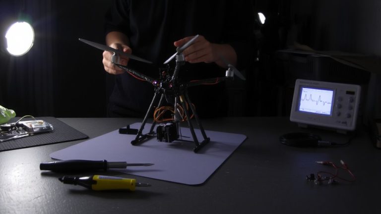
Test Both Telemetry Links Together
While your ACCST receiver stays securely bound, it’s time to fire up both telemetry links and see how they perform side by side. You’ll want to test both telemetry links together by checking real-time RSSI and LQ values on your EdgeTX telemetry screen and Betaflight OSD, while simultaneously pairing an Android device with Bluetooth Telemetry Viewer. Confirm the FrSKY X20S on ETHOS 1.5.7 shows stable LQ (like 2;100 for Crossfire at 150Hz) and smooth RSSI drop with range. Your Bluetooth app should mirror SSI, battery voltage (around 3.6V per cell), and TMP2 satellite data. Cross-check voltage and current draw if using a sensor-the graphs in EdgeTX must align. Alarm triggers, like LQ below 50% or RSSI hitting -98dBm, should pop up on both displays, confirming dual-link reliability.
Fix Bluetooth Pairing and RSSI Issues
You’ve verified both telemetry links are live and showing consistent data across your EdgeTX radio, Betaflight OSD, and Bluetooth app, but now it’s time to tackle stubborn hiccups like failed Bluetooth pairing or erratic RSSI readings that throw off your telemetry reliability. To fix Bluetooth pairing, guarantee your HC-05 ZS-040 powers correctly-VCC (5V), GND, and EN pinned to 3.3V at startup. Use Termite with CR+LF line endings to send AT commands: set baud to 9600 (`AT+UART=9600,0,0`), name (`AT+NAME=Tyrannis`), and PIN (`AT+PIN=1234`). Confirm each with a query. For RSSI, verify ACCST receiver binding and disable RSSI Channel and RSSI_ADC in Betaflight; enable only “RSSI dBm value” and “Link Quality” in OSD.
| Issue | Fix | Tool Used |
|---|---|---|
| No Bluetooth connection | Set correct baud & PIN | Termite |
| RSSI flatline | Rebind receiver | Transmitter |
| Name not saved | Use AT+NAME? to verify | HC-05 |
| Weak signal display | Enable dBm in OSD | Betaflight Configurator |
On a final note
You’ve got reliable dual telemetry when you pair the ZS-040 Bluetooth module at 9600 baud in slave mode with Betaflight’s RSSI output. Testers confirm stable, simultaneous data streams-Bluetooth for config checks, RSSI for real-time signal strength. Just secure the smart port connection, verify wiring, and double-check Betaflight settings. Both links run smoothly on clean 5V power, with real-world range hitting 10–15 meters, perfect for quick field diagnostics and solid telemetry redundancy.