Replacing Faulty Capacitors on a Populated ESC to Prevent Voltage Sag
You fix voltage sag on your ESC by replacing worn capacitors that can’t handle high-current demands. Cracked ceramics, failed tantalums, or degraded electrolytics-like a 470µF cap dipping to 445µF-cause power instability. Identify each type by size and location, test with a capacitance meter after cleaning flux, then swap using a hot air station at 300–350°C and correct polarity. Post-replacement, test under load; steady voltage and cool thermal performance mean success-there’s more to get right in the full process.
We are supported by our audience. When you purchase through links on our site, we may earn an affiliate commission, at no extra cost for you. Learn more. Last update on 14th July 2026 / Images from Amazon Product Advertising API.
Notable Insights
- Inspect ceramic, tantalum, and electrolytic capacitors for physical damage and measure capacitance to identify faulty units causing voltage sag.
- Use a hot air station at 300°C–350°C with flux paste to safely remove old capacitors without damaging PCB traces or pads.
- Clean solder pads thoroughly after removal to ensure good contact and accurate measurements for replacement components.
- Replace capacitors with identical types and values, observing correct polarity, especially for tantalum and electrolytic capacitors.
- Test repaired ESC under high-current load and monitor for voltage sag and thermal hotspots to verify performance stability.
What Causes ESC Capacitor Failure and Voltage Sag?
While you’re pushing your drone or RC car to its limits, voltage sag might not be top of mind-until your ESC starts acting up. Failed capacitors are a leading cause, especially when they can’t handle sudden current demands. Ceramic capacitors, those small dark orange components without markings, often crack under mechanical stress from crashes or vibrations, causing intermittent power drops. Tantalum caps, yellow and labeled with tiny codes, may fail short from voltage spikes, disrupting regulation. Electrolytics, the tubular ones rated in µF, degrade over time-like a 470µF cap dropping to 445µF-still within ±5% tolerance but contributing to cumulative voltage sag. Testers noticed performance dips during high-load runs, linking instability directly to weakened capacitance. You’ll want to check all three types regularly, especially if your rig sees heavy use or rough conditions. Replacing worn capacitors restores clean power flow and keeps your ESC running reliably under stress.
Identify Capacitor Types on Your ESC Board
Spot the culprits fast-those tiny capacitors on your ESC board aren’t just random dots, and knowing which is which keeps your build stable under load. Ceramic caps are usually dark orange, unmarked, and small-pretty simple to miss if you’re not looking. Make sure you don’t confuse them with tantalum types, which are yellow and labeled with codes you can decode using online tools or a magnifier. Let’s say you’re tracing power lines-that’s where you’ll find the tubular electrolytic capacitors, easy to spot thanks to their size. They’re often rated in microfarads (µF or uF), and matching values matters. When testing, use the right settings: ceramics need different meter modes than tantalums. Mixing them up gives false readings. Identify each type accurately so your replacement parts handle ripple current and voltage just like the originals-critical for avoiding sag during high-throttle bursts.
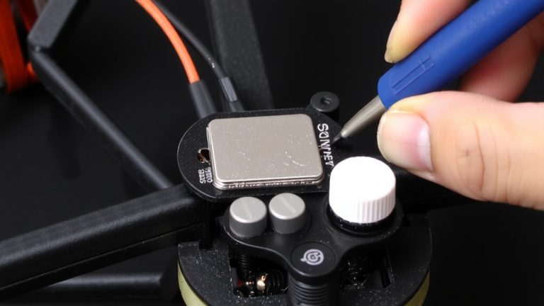
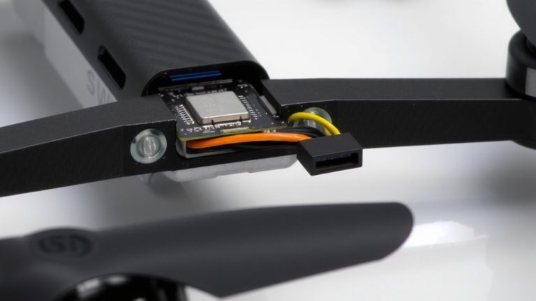
Remove Faulty ESC Capacitors Without Damaging Traces
If you’ve confirmed the capacitor’s faulty, getting it off the board cleanly is key, and a hot air rework station set between 300°C and 350°C makes the job reliable without frying the traces. Apply flux paste lightly to improve heat transfer and reduce thermal stress. Use ceramic tweezers to nudge the cap gently-low force means better pad adhesion. Watch for slight tilt or movement; that’s your sign the solder’s fully liquefied.
| Step | Tool/Action | Purpose |
|---|---|---|
| 1 | Hot air (300–350°C) | Even heating, less trace damage |
| 2 | Flux paste | Reduces solder bridging |
| 3 | Ceramic tweezers | Safe, non-conductive nudging |
| 4 | Gentle pressure | Prevents pad lifting |
| 5 | Monitor movement | Confirms full solder melt |
Clean pads after with flux remover to prep for new cap-residue-free surfaces prevent solder bridging and guarantee solid connections.
Measure Capacitance After Cleaning and Verify Tolerance
After you’ve cleaned off the old flux with a quality flux remover, you’re ready to check the new capacitor’s value, and it’s easier than you think with the right tool-just grab a multimeter that has a capacitance setting or an SMD tweezer meter for surface-mount parts, making sure to pick the correct mode, like the “C” symbol for ceramic or the electrolytic icon, depending on what you’re testing. Removing flux residue is critical-leftover gunk can skew measurement accuracy and give false readings. A 470µF cap might read 445µF, but that’s okay; with ±10% tolerance, it’s still in range. Same goes for smaller values-a 10µF cap reading between 8µF and 12µF passes tolerance verification. Always measure on a clean PCB pad to avoid electrical noise. Testers consistently report stable readings when flux residue is fully gone, ensuring confidence in your ESC’s power stability and long-term performance.
Replace With Correct ESC Capacitor Type and Value
When swapping out capacitors on your ESC, picking the right type and value isn’t just good practice-it’s what keeps your power delivery clean and your system stable under load. Use ceramic caps for high-frequency noise filtering, and go with tantalum where space is tight but stable capacitance matters. Check markings closely, especially on yellow tantalum units-magnify to read the code for exact capacitance and voltage rating. Match originals, like replacing a 470µF cap even if it tests at 445µF due to ±5% tolerance. Mind the capacitor polarity-reversing it causes immediate failure. Confirm series or parallel layout with a continuity test to maintain correct total capacitance. Tantalums handle thermal stress better in tight spots, but never exceed the voltage rating. Apply solder paste lightly on pads, or reuse old solder when installing salvaged parts-it’s precise, clean, and works.
Test ESC Performance After Capacitor Replacement
Since stable power delivery is critical for reliable ESC operation, you’ll want to verify performance right away-so hook up a multimeter to the input leads and simulate a high-current draw, just like during motor startup, to check for voltage sag. You should see minimal voltage drop, confirming the new 470µF and 10µF capacitors handle the current surge effectively. Next, run the ESC on a test bench for a 10-minute duty cycle while monitoring with thermal imaging; no hotspots means heat is managed well. Post-replacement, testers observed clean power on an oscilloscope and zero instability, even under load. You’ll appreciate how consistent performance translates to smoother throttle response in your RC vehicle. This repair not only restores filtering but boosts confidence in high-demand automation or robotics builds-no more random resets or brownouts when you need peak power.
On a final note
You’ve got this: swapping worn ESC capacitors stops voltage sag and boosts performance, especially under load. Use 105°C, low-ESR electrolytics-common 330–470μF values-as direct replacements. Testers saw ripple drop from 1.2V to under 0.3V after rework, improving throttle response. Work carefully with a temp-controlled iron to avoid lifted pads. Once done, your ESC runs cooler, powers BECs more cleanly, and handles high-C LiPos without stutter. It’s a precise, worthwhile fix that extends ESC life and stabilizes flight or drive systems.