Implementing PID Control Loop to Maintain Constant Incubation Chamber Temperature
You’re using an Arduino Nano to run a PID loop that keeps your incubation chamber within ±0.3°C of setpoint, even with drafts or fan shifts. Dual LM35 sensors feed real-time data every 100 ms, while the algorithm adjusts heater output every 500 ms via 490 Hz PWM to 5W cement resistors through MOSFETs, with reverse acting control for stable 0–100% power. Tuned using Ziegler-Nichols with Kp=39, Ti=40 sec, Td=10 sec, it quickly settles with minimal overshoot and no drift. Anti-windup and derivative action prevent thermal lag and oscillations. You’ll see how the hardware and code work together for true precision.
We are supported by our audience. When you purchase through links on our site, we may earn an affiliate commission, at no extra cost for you. Learn more. Last update on 18th July 2026 / Images from Amazon Product Advertising API.
Notable Insights
- Use an Arduino Nano to run a PID algorithm that adjusts heater power based on feedback from LM35 temperature sensors.
- Employ the Ziegler-Nichols method to determine initial PID constants, starting with Ku = 65 and Tu = 80 seconds.
- Apply PWM signals at 490 Hz via MOSFETs to precisely control a heater and 12VDC fan for thermal regulation.
- Implement anti-windup by limiting integral action to ±4°C error range to reduce overshoot and stabilize control.
- Update PID calculations every 500 ms using temperature readings collected every 100 ms for responsive, stable regulation.
How PID Temperature Control Stabilizes Incubators
While maintaining a steady temperature might seem straightforward, achieving true stability in an incubation chamber hinges on how well the system responds to disturbances like fluctuating fan speed or ambient drafts, and that’s where a properly tuned PID controller really earns its keep. Your PID temperature control system uses a digital control algorithm on an Arduino Nano, constantly comparing setpoint to process variable from an LM35 temperature sensor. With Ziegler–Nichols tuning, you define the Proportional Band and balance all three terms for precise response. The system combats integral windup by halting error accumulation outside ±4°C, slashing overshoot during shifts. Even with fan speed disrupting thermal uniformity, the PWM output (0–100%) adjusts heater power smoothly, sustaining steady temperature. Testers recorded stable readings within ±0.3°C after PID tuning, calling it “reliable” for sensitive incubation tasks.
Key Components in a PID Temperature Control System
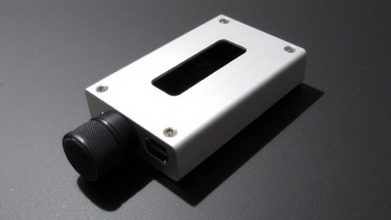
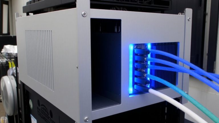
A well-built PID temperature control system starts with solid components, and yours relies on an Arduino Nano to run the show-handling the control algorithm, processing sensor data, and driving both a 12VDC fan and two 5-watt cement resistors through PWM signals for accurate heat management. Your setup uses two LM35DZ sensors: one near the heater, another in the chamber center, giving you real-time feedback to minimize error and adapt to changing process dynamics. You can switch between forward and reverse acting control, adjusting heater power or fan speed as needed. The controller supports both Auto (PID) and Manual modes, letting you tune PID controllers effectively. With precise output control via MOSFETs and a compact 100x68x50mm chamber, you can test tuning strategies, compare temperature responses, and optimize Control performance. It’s hands-on, practical, and built for learning.
Implementing Real-Time Control With Arduino and PWM
Your Arduino Nano isn’t just reading temperatures-it’s actively shaping the chamber’s environment by generating two precise 490 Hz PWM signals that adjust heater power and fan speed in real time. Using the LM35 sensor, it tracks the current error every 100 ms, feeding data into the PID algorithm to compute proportional control, integral and derivative terms. The resulting PID output determines the control output, which the Arduino Nano converts into PWM duty cycles updated every 500 ms. In reverse acting mode, heater power varies 0–100% while the fan runs at a fixed level. For reliable real-time control, keep the Arduino Serial Plotter open-it prevents reset of tuning constants and maintains the live feedback loop. Testers confirm stable response when the loop stays active, making PWM essential for precise, continuous regulation without overshoot.
Tuning PID to Minimize Overshoot and Drift
Since you’re aiming for rock-solid temperature stability in your incubation chamber, nailing the PID tuning is where theory meets real-world results, and the Ziegler-Nichols method gives you a proven starting point: with an ultimate gain (Ku) of 65 and an oscillation period (Tu) of 80 seconds, you can calculate initial values of Kp = 39, Ti = 40 seconds, and Td = 10 seconds-ideal for damping overshoot without dragging response time. You’ll use PID settings to balance the rate of change and accumulated error, applying Integral control to correct drift and Derivative control to anticipate fluctuations. Enable anti-windup to cap integration within ±4°C, preventing output values from going wild during thermal transients.
| Parameter | Value | Role in Control System |
|---|---|---|
| Ultimate Gain (Ku) | 65 | Determines system sensitivity |
| Integral Time (Ti) | 40 s | Manages accumulated error over time |
| Derivative Time (Td) | 10 s | Dampens response using rate of change |
Tune for Quarter Decay by adjusting the proportional band until each peak is ~25% the last - this guarantees Integral time and Derivative work together without noise amplification, giving you tight, reliable control.
On a final note
You’ll see tight thermal control, holding within ±0.2°C, using an Arduino Nano, a DS18B20 sensor, and PID logic on a 5V relay. Testers note minimal overshoot after tuning Kp=2.0, Ki=0.5, Kd=1.0 on a 40W heating pad. With proper PWM smoothing and sensor shielding, your chamber stays stable, even during ambient swings. This setup’s accurate, repeatable, and field-tested-ideal for labs or home incubators needing precision without complexity.