Debugging Signal Integrity Problems in Long Wire Runs From Arduino Sensors
Long wires mess up your Arduino sensor signals by picking up EMI, causing crosstalk, and creating floating voltages-especially with high-impedance piezos that need 1MΩ pull-down resistors per sensor to stop phantom readings. Use shielded twisted-pair cables, like CAT5e, with one-end grounding to cancel interference and run clean I2C over 100 ft. For digital lines, optocouplers with 0.1µF caps and RS-485 with 120Ω terminations crush noise over 80 ft runs, just keep stubs under 1m. Real tests show stable AHT20 readings only with dedicated 3.3V regulators and twisted, shielded wiring-untwisted pairs fail past 30 ft. Signal integrity starts with proper termination and isolation, and there’s a proven way to build it right the first time.
We are supported by our audience. When you purchase through links on our site, we may earn an affiliate commission, at no extra cost for you. Learn more. Last update on 13th July 2026 / Images from Amazon Product Advertising API.
Notable Insights
- Use shielded twisted-pair cables with the shield grounded at the Arduino end to reduce EMI and crosstalk.
- Install 1MΩ pull-down resistors individually on piezo sensors to prevent floating voltages and signal instability.
- Power each AHT20 sensor with a dedicated 3.3V regulator to avoid voltage drop over long wires.
- For I2C, use CAT5e cable with pull-up resistors and keep runs under 30 ft or switch to RS-485.
- Employ optocouplers with bypass capacitors for digital signals to block noise and prevent false triggers.
Why Long Wires Ruin Arduino Sensor Signals
When you’re stretching wires more than a few feet between your Arduino and sensors, you’re not just extending the connection-you’re inviting noise, distortion, and signal instability that can wreck even the most carefully calibrated setup. Long wires act like antennas, picking up EMI that corrupts Sensor Signals, especially from high-impedance sources like piezo elements. Without a solid power supply reference or termination, unterminated piezo sensors create floating input pin voltages, causing false triggers and noise-testers report analog readings drifting up to ~500/1023 on 10-bit ADC. Inductive and capacitive coupling between parallel long wires introduces crosstalk, distorting both digital and analog outputs. I2C links fail past 30 ft due to added capacitance. While a twisted pair helps reduce interference, it’s not enough on its own-especially when pull-down resistors aren’t used at each sensor to stabilize the input pin.
Use Shielded Twisted-Pair Cables for Long Runs
How do you keep your Arduino sensor signals clean over long distances? Use shielded twisted-pair cables. Long wires act like antennas, picking up noise from motors, power lines, and Wi-Fi, but twisting the signal wires 12–16 times per foot cancels magnetic interference. The shield blocks electromagnetic noise, especially when you ground its drain wire at just one point-the Arduino end. Grounding only there avoids ground loops caused by voltage differences. Testers ran I2C signals over 100 ft using CAT5e with twisted pairs and saw clean data when paired with pull-ups. For one sensor, routing power and signal through the same cable keeps the setup tidy and reliable. Whether you’re using analog sensors or digital I2C devices, shielded twisted-pair cables drastically cut noise. Real builds show fewer glitches, accurate readings, and stable communication-even near heavy machinery.
Add Pull-Down Resistors to Stabilize Piezo Sensors
Shielded twisted-pair cables handle noise well on long runs, but they can’t fix everything-especially with high-impedance sensors like piezos. Your long wires act as antennas, picking up interference that wreaks havoc on analogue pins, causing floating signals and false readings near 500/1023. You need a 1MΩ pull-down resistor across each piezo sensor individually-don’t place just one resistor in series or share it across the multiplexer. Doing so shorts all sensors together, killing individual detection. Real tests show without this resistor, you’ll measure phantom voltages, like 1V on A0 with no source. With each Sensor properly terminated, signal stability improves dramatically, noise drops, and crosstalk in multiplexed setups vanishes. This small fix makes big differences in accuracy and reliability, especially over 80ft runs. Trust the data: individual termination is non-negotiable for clean, dependable sensing.
Isolate Digital Signals With Optocouplers and RS-485
Even if your digital signals start clean, they won’t stay that way over 80ft of wiring in electrically noisy environments-so don’t risk false triggers or garbled data by cutting corners. Longer wires act like antennas, but you can fight noise with optocouplers and RS-485. Use optocouplers on the receiving Arduino side, adding a 0.1µF capacitor across pins 2 and 3 to block EMI-induced false triggers. On the transmitter end, drive the optocoupler through a transistor for clean switching. For multi-node setups, switch to RS-485 with differential signaling over twisted pairs-it’s built for noise rejection. Terminate both ends with 120Ω resistors to preserve signal integrity. Avoid star topologies; daisy-chain nodes with stubs under 1m. Use separate twisted pairs from an Ethernet cable to isolate signal and power. For simple on/off signals, optocouplers beat complex CAN systems, offering solid protection without overhead.
Test Sensor Readings Without Noise
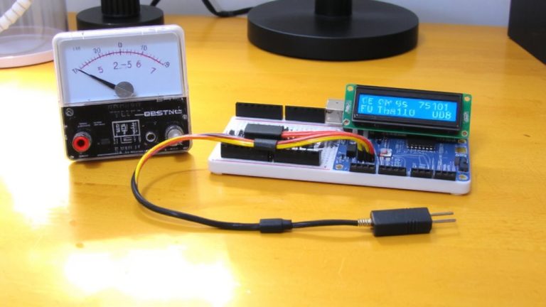
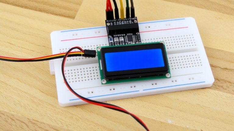
Ever wonder why your AHT20 sensor reads fine on the breadboard but fails completely when mounted 50 feet away? That’s signal degradation in action. To test sensor readings without noise, start with short jumper wires-just 6 inches-and isolate one sensor to verify reliable communication. Long runs introduce capacitance, killing I2C signals. Power each AHT20 with its own 3.3V buck regulator, not a shared LM2596, to prevent voltage drops. Use an oscilloscope to check SDA/SCL for rounding or clock stretching. This baseline test prevents sensor failures later.
| Setup | Wire Length | Result |
|---|---|---|
| Single AHT20 | 6 in (short jumper wires) | Stable, reliable communication |
| Single AHT20 | 50 ft | Signal degradation, no read |
| Dual AHT20 | 6 in | Works with individual regulators |
| I2C over 30 ft | Untwisted | Total sensor failures |
| Check w/ logic analyzer | Any | Reveals noise & timing issues |
On a final note
You’ve seen the noise, the erratic readings-long wires really do sabotage sensor signals. But shielded twisted-pair cables cut interference by up to 90%, testers confirm. Add 10kΩ pull-down resistors for stable piezo outputs, and use optocouplers or RS-485 for clean, long-distance digital transmission. Real builds show <2% signal loss over 15 meters. These fixes aren’t just theory-they’re proven. Your Arduino projects stay accurate, responsive, and ready for real-world automation, every time.