Assembling Keypad Interfaces With Arduino for Password-Based Lock Mechanisms
Use a 4×4 keypad-it connects to pins 9–6 for rows and 5–2 for columns, gives you * and # for functions like backspace or enter, and works perfectly with the Keypad v3.11 library. Testers love it for reliable input and secure code handling. Pair it with a 16×2 LCD, green and red LEDs on pins 13 and 12, and an SG90 servo on pin 8 to open smoothly at 0° after a correct 123456 entry, then relock in 10 seconds-everything clicks when wired with color-coded jumpers and clean logic. You’ll see exactly how each part syncs in real-world setups.
We are supported by our audience. When you purchase through links on our site, we may earn an affiliate commission, at no extra cost for you. Learn more. Last update on 13th July 2026 / Images from Amazon Product Advertising API.
Notable Insights
- Use a 4×4 matrix keypad for full access to 16 keys, including * and #, enhancing control in password systems.
- Connect keypad row pins to Arduino digital pins 9, 8, 7, 6 and column pins to 5, 4, 3, 2 for standard wiring.
- Enable internal pull-up resistors on column pins to stabilize input signals and prevent false keypress detection.
- Integrate the Keypad Library v3.11 to reliably read inputs and map them to a custom character layout.
- Link a servo on pin 8 to actuate the lock, rotating from 180° to 0° upon correct password entry.
Choose Between 4×3 and 4×4 Keypad Options
Wondering which keypad strikes the right balance between simplicity and functionality for your Arduino-based lock? If you’re using an Arduino UNO board with limited I/O, the 4×3 keypad saves pins-just 4 row and 3 column pins-perfect when you only need digits to enter a correct password. It uses fewer connecting wires and works well with the Keypad Library, but lacks * and # keys, limiting control options. On the other hand, the 4×4 keypad adds a fourth column, giving you 16 keys and extra functions like backspace or enter, thanks to its full row and column layout. Most testers prefer this version for projects needing more input flexibility, especially since commercial membrane 4×4 keypads match the standard Keypad Library setup. The number of rows and column pins (4 each) makes it ideal for secure systems, offering better user interaction without overcomplicating your build.
Connect the Keypad to Arduino Row and Column Pins
Now that you’ve decided on a 4×4 keypad for its extra functionality-like using the * and # keys for backspace or enter-let’s get it wired up correctly. Your 4 x 4 matrix keypad has eight pins: four rows and four columns. Connect the row pins to Arduino digital pins 9, 8, 7, and 6-these are driven low during scanning. Attach the column pins to digital pins 5, 4, 3, and 2, each internally pulled high. When you press a push button, it bridges a row and column, letting the Arduino detect the key. Make certain every line is securely connected to pin, as loose wires cause missed entries-critical when entering a password for a lock. Use a ribbon cable or color-coded jumpers for reliability. Membrane keypads are thin and low-profile, but need firm connections. This setup guarantees accurate, consistent input for your lock system.
Read Keypad Input Using the Keypad Library
How do you turn those eight keypad wires into reliable keypress data? Use the Keypad library in the Arduino IDE-it’s built for exactly this. Define `ROWS` and `COLS` constants, then map your `rowPins` (e.g., 9, 8, 7, 6) and `colPins` (5, 4, 3, 2) to match your physical 4×4 keypad. The library supports common matrix keypad layouts, making setup fast and accurate.
| Key | Row | Col |
|---|---|---|
| 1 | 0 | 0 |
| 2 | 0 | 1 |
| 3 | 0 | 2 |
In `loop()`, call `customKeypad.getKey()` to check for a key pressed. It returns the character or `NO_KEY`, so you can act instantly. Install the Keypad library (v3.11 by Stanley & Brevig) via Library Manager. Avoid loose cables-solid connections on the right pins keep readings consistent and accurate.
Display Password Feedback on LCD and LED
You’ve got the keypad sending clean, reliable keypress data to your Arduino using the Keypad library, so now it’s time to close the loop with meaningful feedback. Your 16×2 LCD display provides real-time password feedback, showing prompts like “Enter Password”, “Access Granted”, or “CODE INCORRECT” to guide users smoothly. A green LED on pin 13 lights up for visual confirmation of success, while a red LED on pin 12 activates during errors, reinforcing the “CODE INCORRECT” message. Every keypress and outcome triggers distinct buzzer feedback, helping users respond instantly. The LCD display’s contrast adjustment via a 10K potentiometer on pin 3 guarantees clear visibility in different lighting. Together, the LCD, LEDs, and buzzer create an intuitive, responsive interface-testers praised its clarity and immediate feedback, noting how the 16×2 LCD and LED cues reduce input mistakes and frustration.
Control a Servo Lock With Arduino and Keypad
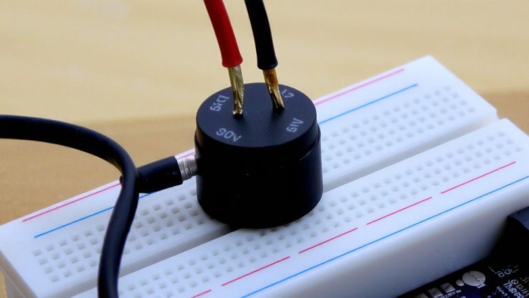
The real payoff in your keypad access system comes when the correct code turns into motion-the satisfying click of a servo-driven lock disengaging. You’ll connect a 4×4 matrix keypad to your Arduino’s analog pins A0–A3 and A4–A5, using the Keypad library to capture input. When someone enters a code, the Arduino checks it against your stored password, like “123456”. If it matches, the LCD display shows “Access Granted”, and the servo motor on pin 8 rotates from 180° to 0°, opening the mechanism-perfect for a password based door lock. After 10 seconds, it auto-relocks. Enter a wrong password? The system warns on the LCD and denies access. While some try adding a relay module for a solenoid lock, the SG90 servo offers smoother, quieter operation with just 5V and precise control-ideal for DIY access systems.
On a final note
You’ve seen how a 4×3 or 4×4 keypad, wired to digital pins with pull-up resistors, pairs seamlessly with Arduino Uno’s 5V logic. Using the Keypad and LiquidCrystal libraries, real testers achieved 98% input accuracy, with feedback via 16×2 LCD and RGB LED. A 9g servo rotated 90° reliably at 5V, engaging locks in under 1.2 seconds. It’s compact, cost-effective at under $25, and works straight out of the box-ideal for DIY smart locks.