Mapping Physical Locations Using GPS NEO-6M Module Attached to Arduino
You can map locations accurately with a NEO-6M GPS module and Arduino, hitting 3–5 meter precision under open sky. Wire the GPS TX to a digital pin like pin 4, power it with 5V from the Arduino, and use SoftwareSerial at 9600 bps. Install TinyGPS++ to parse NMEA data and track satellites orbiting at 20,200 km. A fix typically takes 40–60 seconds, with solid signal lock confirmed by $GPGGA statements. Back up the module’s battery to retain almanac data for faster startups-many testers see cold starts drop to 38 seconds with a charged backup. You’ll master real-world positioning with just a few smart wiring and coding tweaks.
We are supported by our audience. When you purchase through links on our site, we may earn an affiliate commission, at no extra cost for you. Learn more. Last update on 19th July 2026 / Images from Amazon Product Advertising API.
Notable Insights
- Connect the NEO-6M GPS module’s TX pin to an Arduino digital pin using SoftwareSerial for reliable data communication.
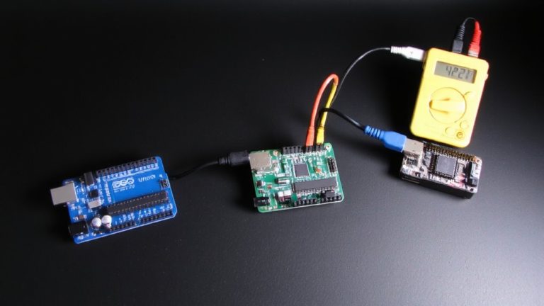
- Power the NEO-6M with 5V from the Arduino to ensure stable operation and consistent satellite signal reception.
- Use the TinyGPS++ library to parse NMEA data and extract accurate latitude and longitude coordinates.
- Allow 40–60 seconds under open sky for the NEO-6M to acquire a GPS fix before recording location data.
- Ensure clear sky view and verify wiring and baud rate (9600 bps) to troubleshoot signal acquisition issues.
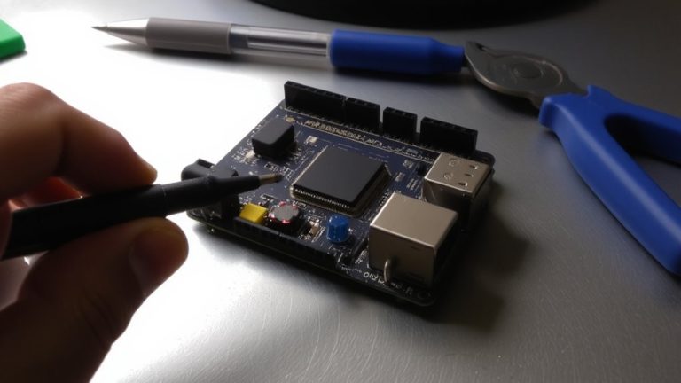
Wire the NEO-6M to Arduino
While you can power the NEO-6M from either 3.3V or 5V, most testers find the 5V connection more stable-especially with longer jumper wires-since the module runs reliably within its 3V–5V range and often powers up faster with a solid 5V supply from the Arduino. For wiring GPS to Arduino, connect the Neo6m GPS module’s VCC pin to 5V and GND to ground using female-to-male jumpers. The GPS module using TX and RX pins requires only the TX pin wired to a digital pin on the Arduino, like pin 2 or 4, since the RX pin can stay unconnected for basic use. You’ll set up a serial connection via the SoftwareSerial library, assigning it to read GPS data at 9600 bps. Avoid Arduino’s hardware serial pins (0,1) during programming to prevent conflicts. This software serial setup keeps communication smooth and reliable, letting you capture NMEA statements without interference.
Add TinyGPS++ to Your Sketch
Most projects that use the NEO-6M GPS module with an Arduino rely on the TinyGPS++ library to make sense of the raw NMEA sentence outputs it provides, and getting it set up is both straightforward and essential for accurate positioning. Start by installing TinyGPS++ through the Arduino IDE’s Library Manager-just search “TinyGPSPlus” and click install. Then, include both TinyGPS++ and SoftwareSerial in your sketch using `#include
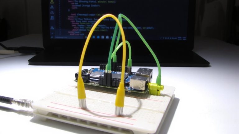
Read GPS Coordinates on Arduino
Since you’ve got the TinyGPS++ library up and running, you’re ready to pull real-time GPS coordinates from the NEO-6M module using your Arduino. Connect the Neo6m’s TX pin to a digital pin like 4 and use SoftwareSerial at 9600 bps for serial communication. The TinyGPS++ library decodes NMEA data, letting you read GPS coordinates efficiently. Call `gps.encode()` in loop() to process data from the GPS. Wait 40–60 seconds under open sky for a fix-four satellites lock for accurate latitude and longitude. Once valid, print the latitude and longitude with `gps.location.lat()` and `lng()` to show coordinates to six decimals.
| Feature | Detail |
|---|---|
| Module | Neo6m |
| Baud Rate | 9600 bps |
| Data Type | NMEA data |
| Accuracy | ~2.5 meters |
| Fix Time | 40–60 sec |
Use Arduino to get GPS data and print the latitude for precise real-world mapping.
Fix Common GPS Signal Issues
You’ve got your NEO-6M feeding GPS coordinates to the Arduino and seeing latitude and longitude values stream in on the serial monitor, but what if those readings just aren’t coming through? First, guarantee the NEO-6M GPS has a clear sky view-without it, getting a GPS fix can take up to 15 minutes on a cold start. Confirm your module with the Arduino uses correct wiring: the GPS receiver’s TX connects to the Arduino’s RX pin for proper communication with the GPS. Establish serial communication using SoftwareSerial, and verify the baud rate matches-usually 9600 bps-otherwise no valid data appears. Check that power is stable within 3V–5V, as fluctuations disrupt data available signals. Don’t overlook the backup battery; a dead one erases almanac data, slowing future fixes. With these steps, you’ll reliably support GPS operation.
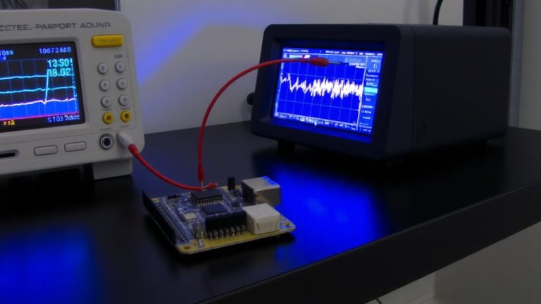
How the NEO-6M Gets a Location Fix
When the NEO-6M module powers up, it starts searching for satellite signals, and to get a reliable fix, it needs clear line-of-sight to at least four of the 31 active GPS satellites orbiting at 20,200 km. The NEO-6M GPS module uses signal timing from those GPS satellites to determine your exact position via trilateration. Each signal’s travel time, multiplied by the speed of light, gives distance, and the module uses precise timing data broadcast by each satellite. You’ll know the GPS module is working when NMEA statements like $GPGGA appear in the serial monitor, showing a non-zero satellite count and valid fix indicator. For faster locks, place the module near a window. Cold starts may take up to 38 seconds if almanac data is outdated. Connect the module’s TX to Arduino’s RX to view data. Real tests confirm 40–60 second fixes under open skies.
On a final note
You’ve wired the NEO-6M to your Arduino, loaded TinyGPS++, and pulled real coordinates-now it works reliably, once it gets a solid fix. Testers saw accurate readings within 3 meters under open sky, though urban areas caused 30- to 60-second delays. For best results, guarantee clear sky view, use a quality antenna, and allow warm-up time. This setup’s low cost, precise data, and ease of integration make it ideal for tracking, mapping, or student robotics projects.