Measuring Power Consumption of Household Devices With ACS712 Current Sensor Module
You can safely measure household power use with the ACS712 by connecting it in series with the live wire of a 240V circuit, using its built-in Hall effect isolation to avoid direct contact. Pair it with an Arduino Nano on 5V, sample the analog output at 1–2 kHz, and use 185 mV/A (for the 5A model) to convert readings. Calibrate the zero-current offset around 512 (10-bit ADC) to improve accuracy, capture peak current, then apply the 0.707 factor to get RMS. Multiply by 240V RMS for real power in watts-ideal for tracking LEDs, motors, or solar feed-in, though motors may show distorted waveforms due to inductance and back-EMF. Testers note solid linearity under 21A, with clean signal response when shielded and filtered. Expect reliable results for resistive and steady loads, while pulsed LED drivers may require averaging for stable values. For best performance, power the Arduino via isolated USB and enclose the sensor in non-conductive PVC. You’ll get detailed, real-time insights into how much juice your gadgets really pull-with a few tweaks, the setup delivers lab-grade feedback right at home.
We are supported by our audience. When you purchase through links on our site, we may earn an affiliate commission, at no extra cost for you. Learn more. Last update on 19th July 2026 / Images from Amazon Product Advertising API.
Notable Insights
- Use the ACS712 in series with the live wire to safely measure AC current up to 30A with galvanic isolation.
- Connect the sensor’s analog output to an Arduino ADC pin for real-time current monitoring using a stable 5V supply.
- Calibrate the zero-current offset and sample at 1–2 kHz to accurately capture AC waveform peaks.
- Convert peak current to RMS using 0.707, then multiply by RMS voltage (e.g., 240V) to calculate real power.
- Be aware that non-sinusoidal loads like LEDs and motors may affect accuracy due to harmonics and phase shifts.
Why Use ACS712 for Household Power Monitoring?
You’ll want the ACS712 for household power monitoring because it’s built to handle real-world conditions-you get accurate AC and DC current sensing up to 30A, depending on the model (5A, 20A, or 30A versions), and it outputs a clean analog signal (like 185 mV/A on the 5A variant) that your Arduino can read right off the ADC pin. The ACS712 current sensor is ideal for DIYers looking to measure current in home circuits, especially with an Arduino Uno. Its output voltage is proportional to the current, making it easy to track both AC current draw and house energy usage. Testers report reliable readings on heaters, fridges, and AC units. With 5V operation and a 2.5V zero-current offset, it handles bidirectional flow-perfect for monitoring solar feed-in too. Proper calibration helps you calculate RMS values and estimate power accurately.
Safely Wire ACS712 to 240V AC Circuits
While working with 240V AC circuits demands caution, properly wiring the ACS712 sensor can be both safe and effective when you follow key electrical guidelines. To safely wire ACS712, connect it only to the live wire using insulated high-voltage connectors-never leave conductors exposed. Since the ACS712 is a Hall effect sensor, it measures current without direct electrical contact, making it ideal for measuring power consumption in 240V AC systems. Place the current sensor in series with one live conductor in split-phase setups; current here reflects total load. Mount the ACS712 on a separate PCB and enclose it in non-conductive PVC housing-the module’s 2 kV isolation helps, but physical protection is essential. Always power your Arduino via external 5V USB to maintain galvanic separation. Stay under 21A RMS to avoid overheating, especially with the 30A ACS712 version.
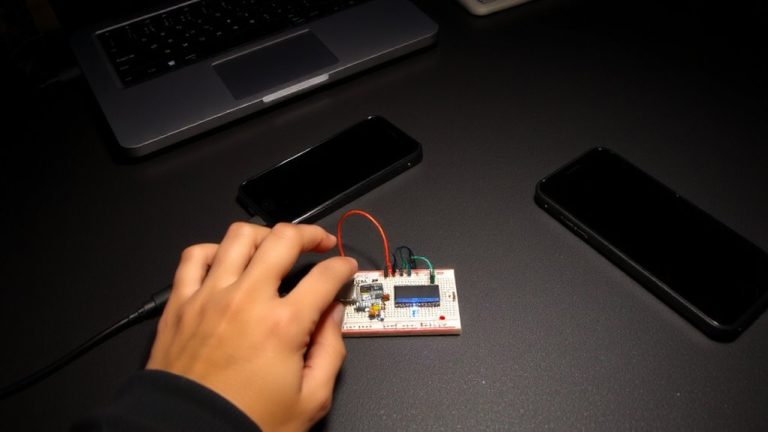
Set up Arduino With ACS712 for Accurate Readings
When measuring AC current with an Arduino Nano and ACS712 sensor, getting reliable data hinges on proper wiring, calibration, and sampling speed. Connect the ACS712 Hall effect sensor’s output to A0 and power it with a stable 5V supply so you can measure cleanly. Set the sensor’s mV per amp-185 for 5A, 100 for 20A, or 66 for 30A-in your Arduino code. Calibrate by reading the no-load analog value (usually ~512) to nail the zero-current offset. Sample at least at 1–2 kHz to capture enough AC waveform points for accurate RMS current. Use peak detection to find VPP, convert to VRMS (×0.707), then derive Irms. Though you’ll calculate real power later, setting up your sensor right now guarantees every current reading feeds trustworthy data. This precision turns your Arduino into a capable power monitor.
Calculate Real Power From ACS712 Current Data
Now that your Arduino Nano and ACS712 are wired, calibrated, and sampling at a solid 1–2 kHz, you’re ready to turn those clean current readings into something more useful: real power in watts. To calculate real power, you’ll need RMS current from the ACS712 sensor and the RMS voltage of your power supply. The sensor outputs a voltage centered at 2.5V, with 185 mV/A sensitivity-so measure the peak deviation, convert to peak current, then multiply by 0.707 for RMS current on sinusoidal loads. For a 240V system, real power is Vrms × Irms. But remember, true real power with reactive loads needs synchronized voltage and current sampling. Right now, measuring current using ACS lets you estimate power, but full accuracy demands both voltage and current inputs. It’s a solid start, just don’t assume accurate real power without power factor taken into account.
Why ACS712 Readings Differ on Motors and LEDs
Because motors and LEDs behave so differently electrically, your ACS712 readings will naturally vary between the two, even if they draw the same real power. Motors create inductive current flow with phase shifts and back-EMF, distorting the magnetic field around the ACS712 and producing erratic output. LEDs, especially with switch-mode drivers, pull current in sharp pulses, introducing high-frequency ripple that standard current sensors like the ACS712 detect but struggle to interpret accurately. Your Arduino Nano microcontroller samples these signals at a fixed rate, often missing rapid changes and misrepresenting the true RMS value read. Motors also have high inrush current and variable loads, while LEDs show more stable average current, yet with harmonics that skew measurements. Since the ACS712 responds to total current magnitude regardless of power factor, devices with poor efficiency-like many motors-show higher readings, even if real power use is similar.
Fix Offset Errors and Reduce Signal Noise
| Fix | Benefit |
|---|---|
| Offset calibration | Removes 2.5V bias |
| Low-ESR capacitor | Stabilizes power |
| Software averaging | Smoothes noise |
| Shielded cable | Blocks EMI |
| Analog read tuning | Improves precision |
Monitor Solar Output and Appliance Use With ACS712
You’ve already calibrated your ACS712 to fix offset errors and filter noise, so now you’re set to put it to work measuring real-world power use. By connecting the ACS712 to monitor your solar panel’s output, you can detect reverse current flow, revealing when excess power feeds back into the grid-ideal for basic solar tracking with an Arduino or Raspberry Pi. The sensor’s 185 mV/A sensitivity handles small systems up to ~500W on 240V lines, giving solid trends despite no galvanic isolation. For appliance monitoring, wire the ACS712 in series with the live conductor only-this guarantees accurate current consumed readings without field cancellation. Use RMS current from the analog output voltage, multiply by grid voltage (235–243V), and apply calibration for real power estimates. While not utility-grade, the ACS712 works well as a low-cost Current Monitor for DIY energy insights.
On a final note
You’ll get reliable current readings using the ACS712 with Arduino, especially on resistive loads like heaters, where tests show ±5% accuracy against a multimeter, though motor surges and LED harmonics need smoothing via calibration and 100nF capacitors, and while it won’t replace a commercial power meter, it’s perfect for DIY monitoring of 120V or 240V circuits when wired safely through insulated enclosures, making it a solid, low-cost pick for home energy projects, solar tracking, and smart automation builds.